Contact Us
Over the years, even the best machines may need occasional service. Positech offers quality parts and expert service and support for both its Positech and Conco equipment. For prompt service, please fill out the form below and a member of our service department will get back to you as soon as possible.
Warranty
Positech manipulators are guaranteed for 12 months on electrical, hydraulic, pneumatic, magnetic and vacuum pats, and for 18 months on mechanical parts. View our Standard Term and Warranty here.
Service Manuals
Contact the Positech Service department for replacement operator service manuals. Service manuals for Positech products (2005-present) are available in electronic format or may be purchased as a hard copy or thumb drive.
Preventative Maintenance
Increase the value of your initial investment. Call (888) 688-0020 to extend the life of your machines with our preventative maintenance program.
Refurbishing Positech Machines
Positech can rebuild an entire manipulator including the end-effector. Positech also rebuilds manipulator components which includes, but not limited to, hand controls, control circuits, cylinders, and replacement parts. This service can cave up to 50% compared to the cost of purchasing a new machine.
Installation Services
To assure a safe, efficient installation, Positech can supply supervised installation, either turnkey or by partnering with you with local contracted installation personnel or your internal maintenance personnel.
Spare & Replacement Parts
Custom and standard parts are available. Positech suggests stocking the items on your recommended spare parts list, found in the operator's service manual. Inquire about availability at (888)688-0020.
JD Neuhaus
Positech is also a JD Neuhaus factory-trained hoist repair service provider.
Frequently Asked Questions
- The initial settings will be for the machine and empty tooling, so remove any payload and position the arm in mid-stroke.
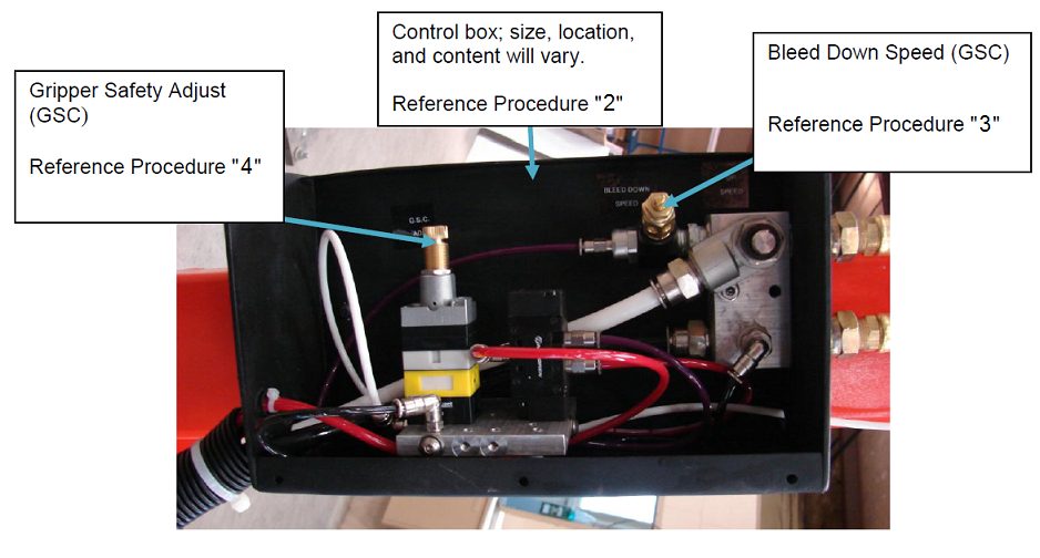
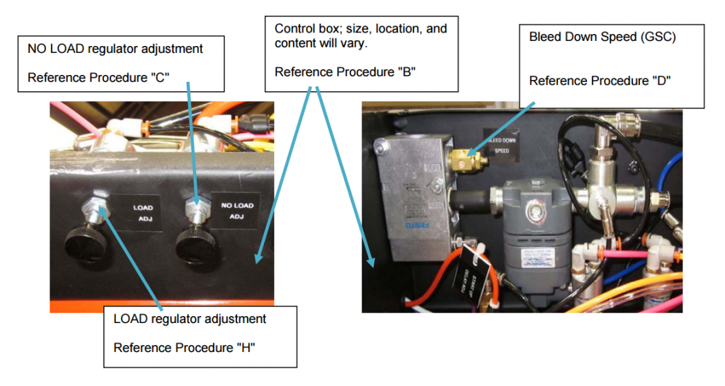
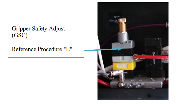
- Remove the cover of the control box (typically a 4" x 6" by 12" to 16" long box mounted on the manipulator) and locate the control valve tagged as "Bleed Down Speed" and the valve tagged as "GSC Adj."
- Find the flow control valve tagged as "Bleed Down Speed," which is located with the valves in the control box. CAUTION: The "Bleed Down Speed" flow control valve must never fully open because the valve must create a pressure differential (back pressure), which is sensed by the GSC. The flow control should not be more than about 1/2 open; less usually gives a satisfactory lowering speed with a gripped load.
- Loosen the locknut on the GSC Adj. With the arm in mid-stroke, supporting only itself and tooling, unscrew the adjusting stem until the valve pops. CCW, but not completely out. Screw the stem in until it pops again. CW. Then turn in, 1/4 to 1/2 turn more. Finger tighten the locknut.
- Mechanically attach a payload (test weight) which is close to the minimum GSC rating of your machine.
- Make sure the area around the arm (tooling) is unobstructed when you move the mechanical payload (test weight) to about 6 inches above a suitable set-down surface. Push and hold the RELEASE/RELEASE PROOF push button. The arm should lower, but the gripper should not release until the payload is down and supported. If the lower speed is not satisfactory, adjust the flow control (Bleed Down Speed) so the arm and gripped load lower at a satisfactory rate when you push and hold the release/release proof pushbutton. If the gripper opens before the load is adequately supported, unscrew the steam on the GSC Ajd. a small amount to change the sensitivity. Repeat as much as necessary, but you will reach a point where the gripper will not function when it is empty. Therefore, you need to make your final adjustment so the gripper operates when in mid-air and empty and doesn't operate when the arm is moving down with a gripped load. Once you verify that the gripper won't drop a load in mid-stroke, you can test with the the gripped load higher than 6 inches above the support surface.
- Once the valves are satisfactorily adjusted, gently lock the, but be sure the setting doesn't change while they are being locked. Recheck for proper operation after the valves are locked.
- Replace the cover on the control box.
- The initial settings will be for the machine and empty tooling, so remove any payload and position the arm in mid-stroke.
- Remove the cover of the control box (typically a 4" x 6" by 12" to 16" long box mounted on the manipulator) and locate the control valve tagged as "Bleed Down Speed" and the valve tagged as "GSC Adj."
- Set the NO LOAD balance regulator to properly support the arm and empty tooling. Any time the no load regulator is changed or adjusted, the GSC valve needs to be reset as well.
- Find the flow control valve tagged as "Bleed Down Speed," which is located with the valves in the control box. CAUTION: The "Bleed Down Speed" flow control valve must never fully open because the valve must create a pressure differential (back pressure) which is sensed by the GSC. The flow control should not be more than about 1/2 open; less usually gives a satisfactory lowering speed with a gripped load.
- Loosen the locknut on the GSC Adj. With the arm in mid-stroke, and the NO LOAD regulator properly set, supporting only itself and tooling, unscrew the adjusting stem until the valve pops; CCW, but not completely out. Screw the steam in until it pops again (CW), then turn in 1/4 to 1/2 turn more. Finger tighten the locknut.
- Mechanically attach a payload (test weight) which is close to the minimum GSC rating of your machine.
- Grip test weight and activate LOAD toggle switch (if equipped), or active part present valve (if equipped).
- Set the LOAD balance regulator to properly support a test weight which will be closest to the minimum GSC rating of your machine. You can use your actual payload for the test weight, but if the gripper should release the load before it is supported, the arm (tooling) may move rapidly upward, which can be dangerous.
- Make sure the area around the arm (tooling) is unobstructed when you move the mechanical payload (test weight) to about 6 inches above a suitable set-down surface. Push and hold the RELEASE/RELEASE PROOF push button. The arm should lower, but the gripper should not release until the payload is down and supported. If the lowering speed is not satisfactory, adjust the flow control (Bleed Down Speed) so the arm and gripped load lower at a satisfactory rate when you push and hold the release/release proof pushbutton. If the gripper opens before the load is adequately supported, unscrew the stem on the GSC Adj. a small amount to change the sensitivity. Repeat as much as necessary, but you wil lreach a point where the gripper will not function when it is empty. Therefore, you need to make your final adjustment so the gripper operates when in mid-air and empty and doesn't operate when the arm is moving down with a gripped load. Once you verify that the gripper won't drop a loan in mid-stroke, you can test with the gripped load higher than 6 inches above the support surface.
- Once the valves are satisfactorily adjusted, gently lock the, but be sure the setting doesn't change while they are being locked. Recheck for proper operation after the valves are locked.
- Replace the cover on the control box.
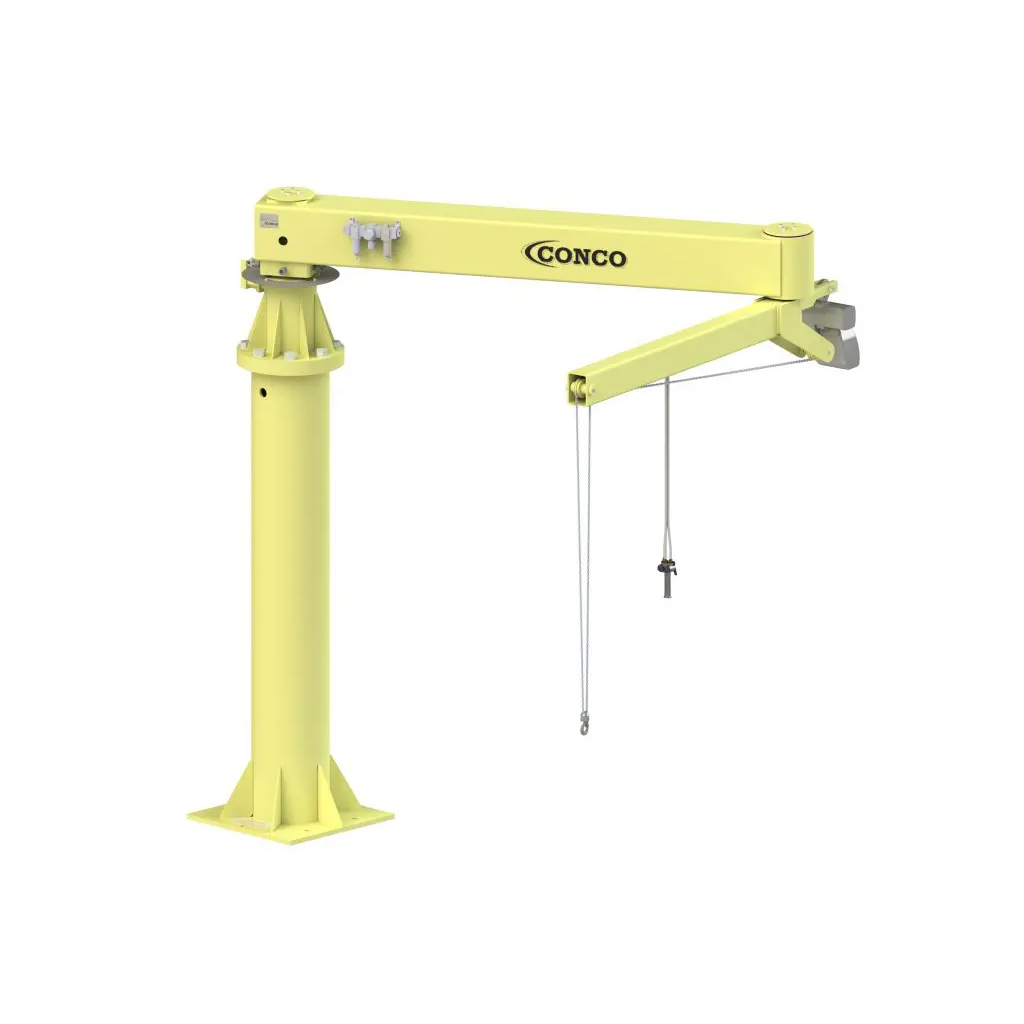
Design: Positech articulated jibs are designed wtih a 5:1 factor of safety to the ultimate strength of the material. The maximum allowable deflection in the jib is 1/8 degree per axis or 1/4 degree total.
Material Standards: All plate steel used is a minimum of ASTM A-36. All steel tubing is ASTM A-500.
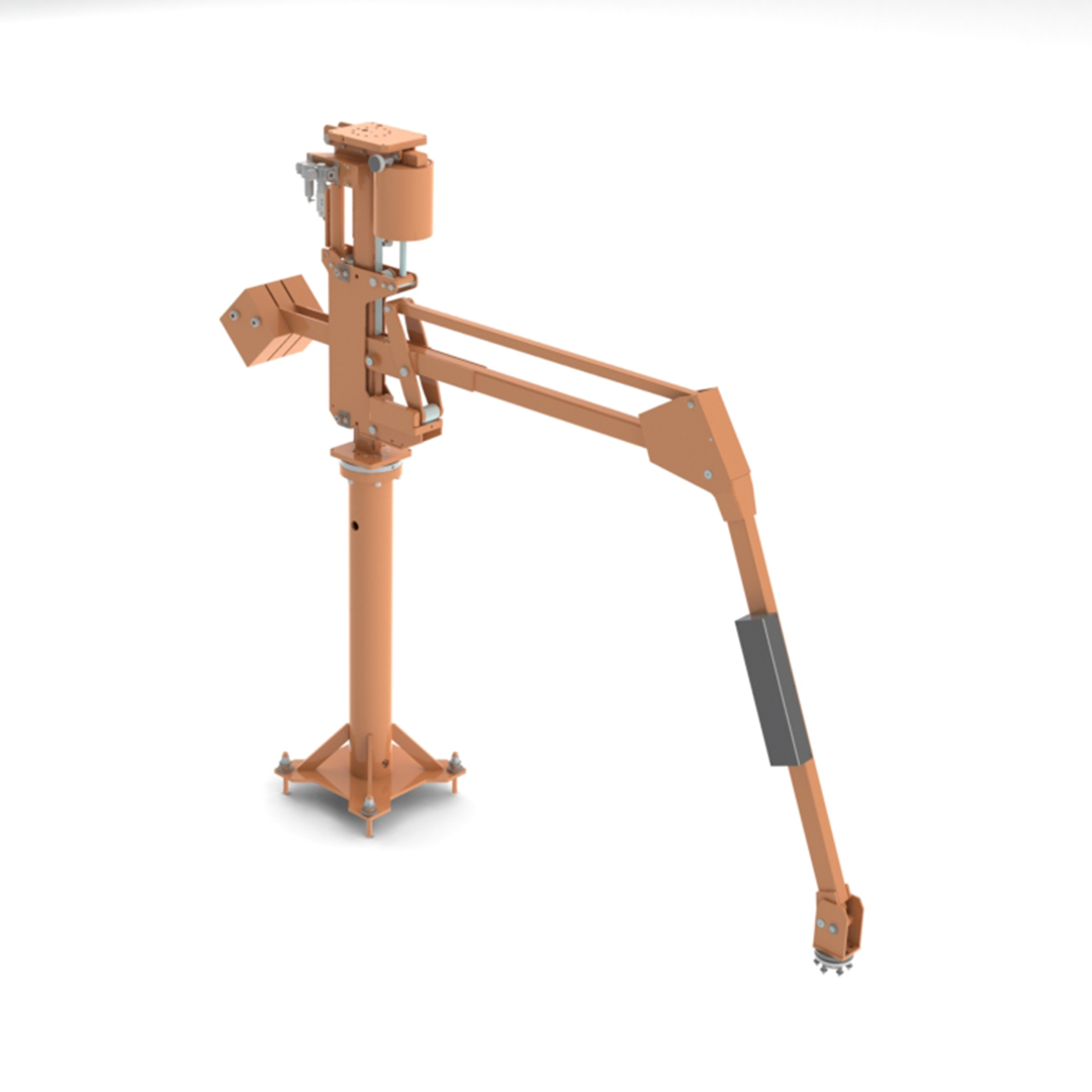
Painting:All steel components are shot-blasted and cleaned with aqueous based solvent prior to painting. Parts will be painted with two-part polyurethane painted to a minimum of 2.0 mil thickness. Standard color is safety orange.
Fabrication:All welding conforms to AWS D1.1 (Structural Welding Code), AWS D1.2 (Structural Welding Code-Aluminum), and AWS D14.1 (Specification for Welding of Industrial and Mill Cranes and Other Material Handling Equipment).
Standards Used (As they apply to jib cranes):
- OSHA Machine guarding - 1910.212
- ASME B30.20-1999 Below the Hook Lifting Devices
- ASME B30.16-1998 Overhead Hoists - Underhung
- ASME B30.17-1998 Monorails and Underhung Cranes
- ISO-12100-1-2003 - Safety of Machinery - Basic Concepts, general principles for design - Part 1: Basic terminology, methodology
- ISO-12100-2-2003 - Safety of Machinery - Basic Concepts, general principles for design - Part 2: Technical Principles
- ISO-13852-1: 1996 Safety of Machinery - Safety distances to prevent danger zones being reached by the upper limbs
- ISO 9001:2015 Quality Management Systems
- 98-37-EC Safety of Machinery
If you would like to open a PDF of our Articulated Jib Design Standards, click here to open.
Optimal performance of pneumatic equipment is dependent on the proper sizing of the air system supplying it. This includes the sizing of the compressor, tank, and feed lines. The crucial imitation of all systems is the amount of air consumption the pneumatic equipment requires. Both continuous and intermittent consumption demands should be considered. All parts of the air system need to be adequate for the consumption required or performance will suffer. The information below outlines how to roughly size an adequate air system. All systems are different and the manufacturer of the system components should be consulted for specific applications
Pneumatic Nomenclature:
- SCFM - Standard Cubic Feet per Minute: This is the flow of air at standard conditions; 70°F (21°C), 14.7psia (101kPA), 0% RH
- ACFM - Actual Cubic Feet per Minute: The flow of air at any reference point. Needs to be definied further for pressure temperature.
- FAD - Free Air Delivery. Actual quantity of air compress converted back to the inlet conditions of the compressor. Standard Inlet Conditions from ISO 1271 68°F (20°C), 14.5psia (100kPA), 0% RH
- ICFM - INlet Cubic Feet per Minute: Same as FAD
- PressureMAX - Maximum Set Pressure of Compressor (Shut off set point)
- PressureMIN - Minimum Set of Pressure of Compressor (Start set point)
- PressureINLET - Pressure at inlet of Compressor (Atmospheric)
Air Compressor Size:
- Consider PSI Requirements - 0-80 psi: a single stage compressor is adequate; 80-250 psi: a two stage compressor is recommended
- Air Consumption: list all requirements in SCFM for ease of calculation, consider both continuous and intermittent usage
- Compressor Horsepower: determine total SCFM, add approximately 20% for system variables, be sure to consider future expansion needs
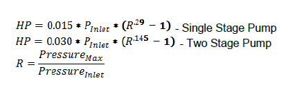
- For 100 psi system requirements: Divide the total SCFM by 4 to get horsepower required for a single stage pump; divide the total SCFM by 5 to get horsepower required for a two stage pump
- For any other system pressure equipment, use the following equations:
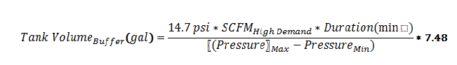
Tank Sizing: As a general rule - the larger the tank, the better the system. A good rule of thumb is enough capacity for 1 minute of compressor capacity.
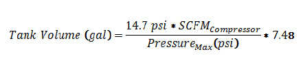
If you have a high flow, low duration air demand, the tank will need to be sized to have enough buffer to avoid a low pressure situation.
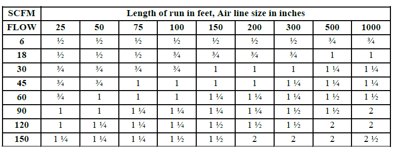
Air Line Sizing: The proper line size of the air supply line is critical to the proper performance of your tool. As the length of the air line from the compressor to the tool, the pressure at the tool will decrease if the line size is too small. Below is a table of recommended line sizes for various line lengths and airflows.
If you would like to open a PDF on Air System Sizing, click here to open.
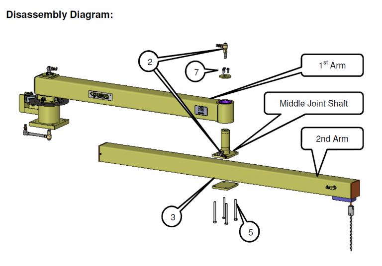
- Turn off air pressure to the unit and lock-out tag-out according to company procedure.
- Disconnect air hose from fitting at the base and end of the middle joint pin.
- Support the second arm with a forklift or something comparable in the middle of the arm.
- Support the second arm from falling during removal.
- Remove the wires and Hex Head bolts. Remove end cap.
- May need to hammer MJ shaft to remove. Use soft face hammer.
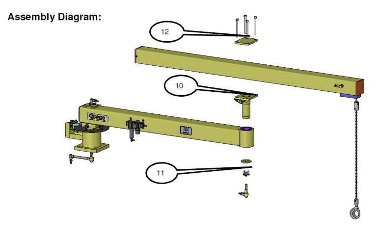
- Insert second arm with arm down, making sure bearings are fully seated in first arm bearing housing.
- Hammer center of second arm shaft to install. Use soft face hammer.
- Re-install end cap, Hex Head bolts, and wires into top of shaft.
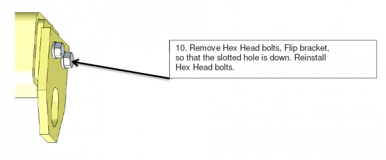
- Remove Hex Head bolts, flip bracket, so that the slotted hole is down. Reinstall Hex Head bolts.
- Connect pneumatic hose to middle joint shaft fitting securely. Apply small amount of thread sealer during install.
- Verify hoses and fittings clear the arm when rotating.
- Turn on air pressure to unit. Verify leak free connections.
If you would like to open a PDF of our Modifying an AJ from Overslung to Underslung FAQ, click here to open.
- Turn off air pressure to the unit and lock-out tag-out according to company procedure.
- Disconnect air hose from fitting at the base and end of the middle joint pin.
- Mark plate location on second arm for easier installation after removal.
- Support the second arm with a forklist or something comparable in the middle of the arm. Secure the arm to the forks, or lift slings evenly.
- Loosen and remove the wires and bolts that secure the Middle Joint Shaft to the second arm. Safely lower the second arm from the connection.
- Support the Middle Joint Shaft from falling during removal.
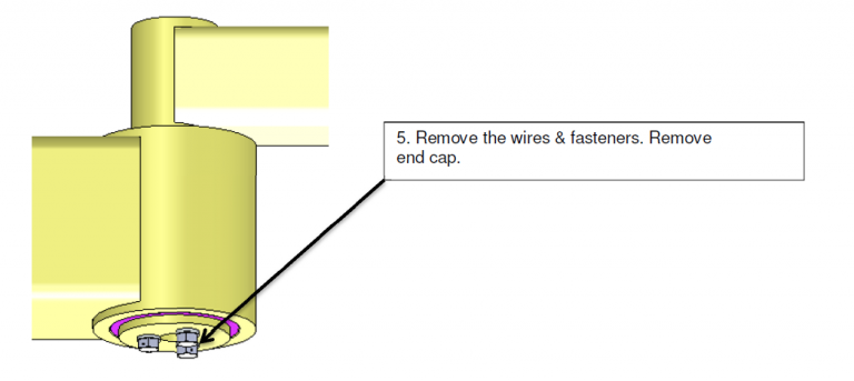
- Loosen the wires and fasteners. Remove end cap.
- May need to hammer Middle Joint Shaft to remove. Use soft face hammer.
- Insert Middle Joint Shaft with flange facing up, making sure bearings are fully seated in first arm bearing housing.
- Hammer center of flange to install. May need bar or C-Clamp to install if hammer is not successful. Use soft face hammer.
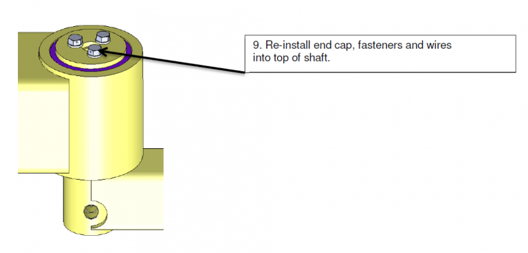
- Re-install end cap, fasteners, and wires into top of shaft.
- Raise second arm into preferred mtg. position, reinstall at marked location from Step #3. Connect mtg. plate fasteners and wiring to end shaft end.
- Connect pneumatic hose to Middle Joint Shaft fitting securely. Apply small amount of thread sealer during install.
- Verify hoses, fittings, and schematics clear the arm when rotating.
- Turn on air pressure to unit. Verify leak free connections.