Already have an idea which application you want? Fill out a RFQ to get in touch
- Home
- Products
Positech machines are designed and built from the ground-up dependent on your specifications and requirements.
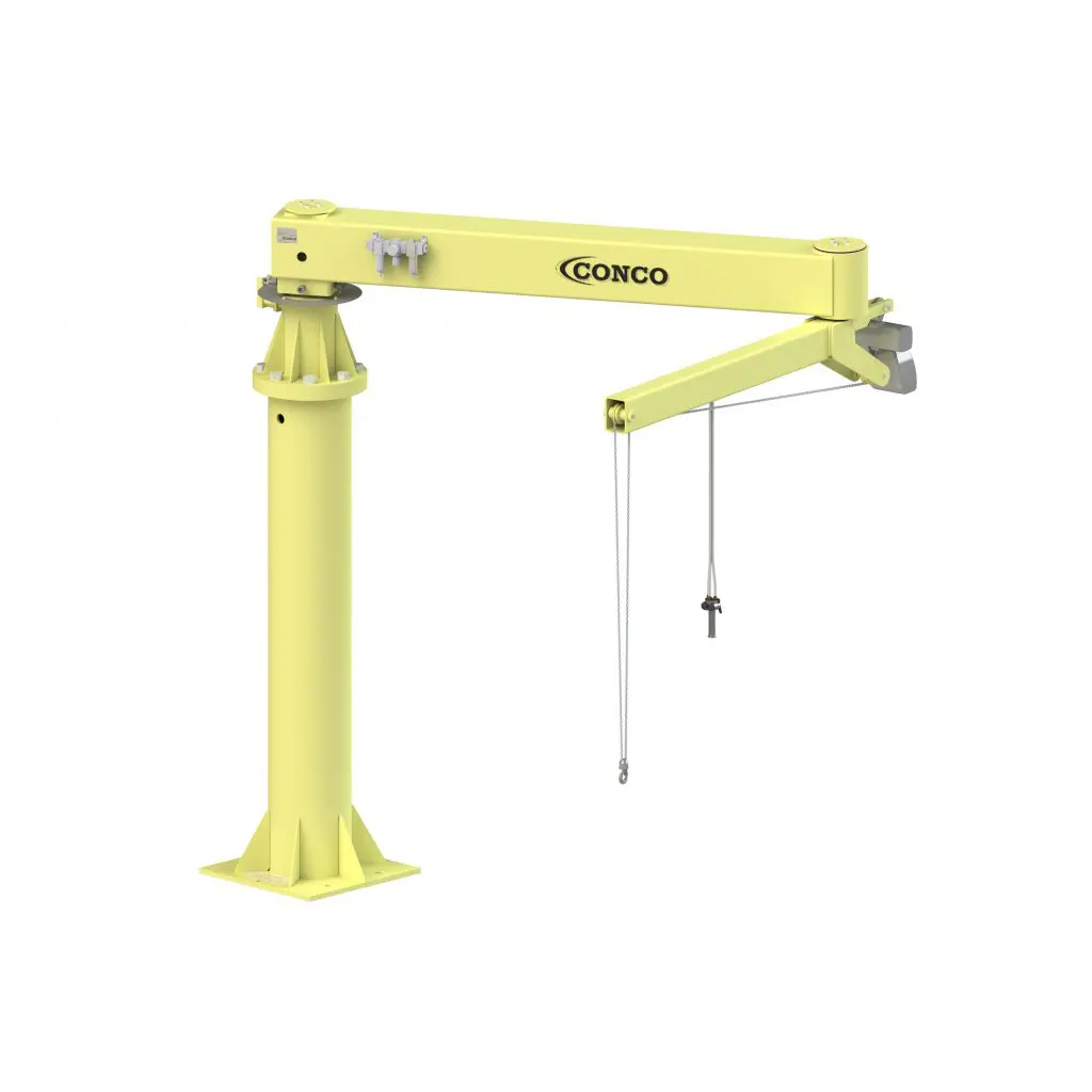
Our Conco line of products feature standard products with quick leadtimes that will get your operation up and running as quickly and efficiently as possible.
Does your application require something outside of your regular industrial manipulator? We'll work with you to custom design application solutions that will be exactly what you need.
Beyond our base machines, Positech can also custom design end-effector tooling that will meet your part and operator needs. Tooling can include specialized pneumatic, electric, and hydraulic circuitry.
- Solutions
- About
- Support
- Careers
- Contact Us
Engine Handling
- Industry: Agriculture, Construction, Military and Defense
- Challenge: Engine Handling
Operators were using a chain and hoist solution to transfer parts. It was deemed an unsafe environment with several dropped parts. Accurate placement in workstation positioners and pallets could not be achieved. Operators were not meeting cycle times with prior handling method.
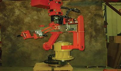
- Industry: Metal Fabrication, Tire
- Challenge: Engine Handling
Multiple parts to be handled. The dunnage and bell housing create clearance restrictions above, below, and around the part. This leaves the face of the flywheel as the only exposed surface for gripping. The gripper cannot interfere with power tool access for driving in the attachment bolts. The entire process must be completed within a 54 second cycle time.

- Industry: Automotive
- Challenge: Engine Handling
Existing hydraulic manipulator was not as effective at placing bars on the paint line hanger as a pneumatic manipulator would be. The “float” capability of a pneumatic manipulator and ease of maintenance convinced the customer to replace their hydraulic manipulator.
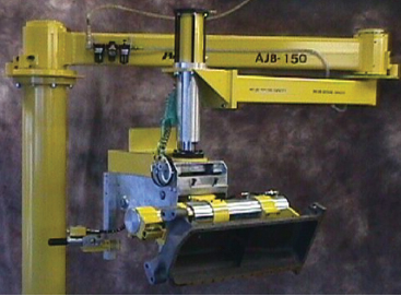
- Industry: Agriculture, Construction, Military and Defense
- Challenge: Engine Handling
The system capacity rating must be able to accommodate larger oil pans that may be manufactured at a future date. The radial reach and capacity requirements create significant moment loads. Work Cell contains obstructions and low headroom.
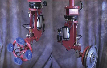
- Industry: Agriculture, Construction, Military and Defense
- Challenge: Engine Handling
Two machining centers in a 16′ x 16′ work cell. One operator is expected to keep the manufacturing process at peak efficiency while manhandling light, but rather large 20″ diameter parts. The safety and ability of the aging workforce to maintain the required cycle time parameters of the work cell led the end-user to seek an ergonomic solution to this material handling problem.
- Industry: Agriculture, Construction, Military and Defense
- Challenge: Engine Handling
Heavy parts were being mounted to an engine on a hanging conveyor and engines are allowed to sway. Operators had to crawl under the engine to insert shields onto installed housing with only 6″ clearance.
- Industry: Metal Production
- Challenge: Engine Handling
Long parts are laying horizontal on the welding table at a 30° down angle. The catalytic converter is towards the operator. Parts are placed into the rack vertically and the catalytic converter is away from the operator at at a 15° forward angle. Intake tube on the bottom of the part is lifted over and onto a 3″ stud. exhaust tube snaps into clips at the top of the rack.
- Industry: Agriculture, Construction, Military and Defense
- Challenge: Engine Handling
Pins are transferred in and out of machining centers, each with its own clearance problems dictating where the pin can be gripped. Customer’s machine operators are apprehensive concerning manipulators. End-effector must be lightweight, simplistic, operator-friendly and safe to use.
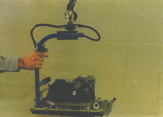
- Industry: Agriculture, Automotive, Construction
- Challenge: Engine Handling
Device must handle a variety of parts and part weights. Close work area makes it impossible to use a floor-mounted unit. Cycle time is short.